
6 Delta Robots and their Applications to Manufacturing
Payton Engelking
Chapter 6. Delta Robots and their Applications to Manufacturing
6.1 Introduction
6.1.1 Origin and Description
6.1.2 Differences Between Delta Robots and Other Manufacturing Robots
6.1.3 General Applications Overview
6.2 Control and Operation
6.2.1 Forward Kinematics of the Delta Robot
6.2.2 Inverse Kinematics of the Delta Robot
6.2.3 Considerations for Motion Control
6.3 Applications to Manufacturing
6.3.1 End Effector Selection
6.3.2 Peripheral Equipment
6.4 Summary
6.5 Practice Problems
Delta robots are commonly found in many industries, particularly in many manufacturing facilities worldwide. Their unique structure lends them to be highly capable in applications where speed and precision are of utmost importance. The motion control of these robots differs from other common manufacturing robots due to constraints on their movement, but control is still performed with standard controllers and motors used in many manufacturing applications. These qualities lend Delta robots to be a common fixture in many manufacturing processes, and a contributor to the advancement of automation and robotics in manufacturing.
6.1 Introduction
Manufacturing robots have been commercially available since 1954, starting with the “Unimate” robot, which was first implemented in 1961 [1]. Since the emergence of manufacturing robots, many different forms of manipulators have been implemented in manufacturing, including Cartesian robots, articulated robots, SCARA robots, and even combinations of each type for more complex manufacturing capabilities. The manipulator we will be discussing is the “Delta” Robot, a style of parallel robot colloquially referred to as the “Spider Robot” for its long, spider leg-like arms driven by overhead equipment. These manipulators have many applications in manufacturing, from simple pick-and-place to high repeatability, high-speed applications [2].
6.1.1 Origin and Description
The Delta robot was invented and developed by Dr. Reymond Clavel in response to a pick-and-place task for palletizing chocolates. It was determined that a new style of robot whose design was not based on biomimicry was needed for this application. From these constraints, the parallel Delta robot was developed [3]. Delta robots are distinct from other robots in their structure, as the links and joints of the delta robot are not in series, but oppose each other and move synchronously as shown in Figure 6.1. This structure provides the Delta robot 3 degrees of freedom and high-speed capability. The Delta robot provides freedom in the x and y directions, but limited freedom in the z direction. This style of robot requires the use of a two link arm, with the upper arm connected to a servo motor and the lower arm connected to the upper arm and base plate (a fixture for attaching the end-effector). This configuration requires high torque motors to operate the system effectively, and due to the long lower arm and requirement of high speed, the end-effector is limited in its payload capacity. This limit on payload also applies to the complexity of end-effectors, as heavy-duty mechanical grippers or other heavy end-effectors will drastically reduce the speed and payload capacity of the manipulator.
“DeltaRamki.gif” by Fridel Selitsky is in the Public Domain, CC0
6.1.2 Differences Between Delta Robots and Other Manufacturing Robots
Delta robots are typically best used in high-speed, high-repeatability applications for items or products of relatively low mass. This high speed and high repeatability are achieved by the constraints of the joints of the Delta robots, as well as the motors which drive the Delta robot. There are many differences between Delta robots and other common manipulators used in manufacturing applications. Manipulators are typically classified by the number and type of joints they contain. Joints are classified as either prismatic (P) joints, which translate along an axis in space and have 1 degree of freedom (DoF), or revolute (R) joints, which rotate about an axis and have 1 DoF. The other types of robots commonly used in manufacturing are as follows:
-
- Cartesian (PPP) Robots
“Descartes configuration.png” by Nikola Smolenski is licensed under CC BY-SA 3.0
Cartesian robots are commonly used in 3D Printing and other additive manufacturing, Computer Numerical Control (CNC) machining, palletizing, and simple pick-and-place tasks. Cartesian robots are classified by their three prismatic joints, with one joint translating along the X, Y, and Z axes as shown in Figure 6.2 Like Delta robots, Cartesian robots typically take up a lot of space, but the workspace of the Cartesian robot is equivalent to the space the robot takes up. A Delta robot occupying the same physical space as a Cartesian robot would have a significantly smaller workspace. Since Cartesian robots are simply supported along the x and y axes, they are able to sustain higher payloads than Delta robots, and are beneficial in use cases where a high payload capacity is required. Due to their movement behaviors, however, these manipulators do not move as quickly as Delta robots.
-
- Articulated (RRR) Robots
Articulated robots mimic the structure of the human arm from the shoulder down, so these robots are typically used for repetitive tasks that require motions typically performed by humans, such as welding, general handling of tools and objects, and assembly tasks. The robot includes three revolute joints configured as shown in Figure 6.3. These manipulators are more complex to control as each joint is suspended in space by the previous joint. This makes the manipulator slower than the Delta robot. Due to the reduced velocity requirement, the articulated robot has the capacity to be built for a higher payload. Articulated robots are typically classified as RRR robots because the first three joints are rotational, but these can include more than 3 rotational joints to achieve more complex movement. As the movement of these robots becomes more complex with more joints, however, the payload capacity decreases.

Created by Payton Engelking
-
- SCARA (RRP) Robots
Selective Compliance Assembly Robot Arm (SCARA) Robots have two revolute joints and one prismatic joint configured as shown in Figure 6.4. These robots are simple to control, have a near cylindrical workspace, but are limited in their motion in the Z direction by the structure of the robot. SCARA Robots are faster than Cartesian robots, but not faster than Delta robots. These manipulators are typically used in material handling, assembly, and shorter-distance pick-and-place applications.

“SCARA configuration.png” by Nikola Smolenski is licensed under CC BY-SA 3.0
6.1.3 General Applications Overview
Delta robots are commonly used in manufacturing for their nimble, repeatable, and high velocity motion. These robots are unique in that they are able to place parts, group objects, and perform general assembly tasks at a high velocity and high repeatability, but are limited by their payload capacity. This combination of attributes makes the Delta robot an ideal candidate for handling small, lightweight, or delicate parts. The Delta robot for these reasons is typically found in food and dietary ingredient handling, pharmaceuticals, and small mechanical and electrical parts manufacturing. The payload capacity of the Delta robot is the other significant constraint associated with these manipulators. The long, lightweight lower arms of the Delta robot are strong, but with the significant accelerations that are experienced by the end-effector, and the length of the arms, the arms are at risk of breaking if overloaded. End effectors have a significant impact on the ability for the Delta robot to perform certain tasks, and if light enough, can expand the types of tasks that the manipulator can perform. For example, a small, telescoping end-effector could give the Delta robot the ability to quickly move to a location of interest, and inspect that location for proper installation of a part. For this reason, the selection of end-effectors is almost as important as the selection of the manipulator carrying the end-effector, as the ability of these two items in tandem determines the success of a system overall.
6.2 Control and Operation
The operation of Delta robots begins at the “base” of the robot, which is typically above the workspace of the manipulator (as seen in Figure 6.5).
The parallel manipulator’s base contains three to four servo motors dependent on the use of the robot. Some models of Delta robots use up to five servo motors, as these models contain four parallel arms instead of three. Servo motors are used in this application to provide the manipulator with feedback control, a critical subsystem of the operation of these robots. Without feedback control, the speed and repeatability of this style of robots are subject to catastrophically fail in the case of minor errors in locating each arm of the manipulator. The Delta robot is typically configured with three arm assemblies. The arm assembly consists of the upper arm which is attached to the servo motor above and the lower arm below, then the lower arm, which attaches to the base plate that houses or mounts the end-effector (dependent on application).
The upper arm of the robot is the link that drives the Delta robot system. High torque servo motors are required to obtain the speeds necessary for these applications, dictating the need for the structure of the upper arm. The upper arm is larger in diameter than the lower arm to withstand the high angular accelerations applying a radial load on the upper arm. The motors act synchronously in small angular increments to achieve the desired motion by the base plate. The length of the arm assembly allows for incremental angular motion of the servo motor to result in high-velocity travel over longer distances by the end-effector.

“Robot delta FlexPicker d’ABB.png” by Marc Auledas is licensed under CC BY-SA 4.0
The lower arm of the delta robot is the link that drives the base plate and end-effector. The lower arm of the robot is typically made of composites like carbon fiber or similar to reduce the weight of the assembly while retaining strength and flexibility. The lower arm assembly is shaped in a parallelogram, with two sets of axial joints to allow for movement of the base plate and end-effector that ultimately keeps the end-effector stable and level during movement of the end-effector. The lower arm is loaded axially by the upper arm, driven by the servo motor, and is loaded in varying intensities of radial and axial loads via the base plate and end-effector depending on the location of the base plate within the workspace and acceleration of the base plate. These varying load cases drive the need for an isotropic or quasi-isotropic material such as carbon fiber that will resist both axial and radial loads.
The workspace of the Delta robot is constrained by the length of the lower arm, the length of the upper arm, and the angular range of the servo motor. The servo motor has the ability for full 360° angular motion but is limited to less than this due to the structure of the Delta robot. The amount of angular motion permitted by the structure of the base of the manipulator is the main factor determining the maximum displacement in the Z direction (assuming the XY plane is parallel to the base plate of the robot in a zero-energy state). As the end-effector travels to the edges of the workspace in the XY plane, the robot loses the capacity for full motion normal to the XY plane. [8] [9]
FIGURE 6.6 A video of the motion of an ABB Delta Robot. [13]
“Robotics Simulator: Simulation of the ABB IRB360 Robot in V-REP” by Coppelia Robotics is licensed under CC BY 4.0

Created by Payton Engelking based on information from [10]
Before the forward and inverse kinematics (FK and IK) models for the Delta robot are discussed, we must first discuss some geometric information about the Delta robot pertinent to the solution of both the FK and IK equations. The first of these is the solution to the locations of the revolute joints on the fixed base of the delta robot, described in Figure 6.7 and Figure 6.8 as B1 , B2 , and B3 .From the conventions shown in Figure 6.6, we can see that the locations of the joints are as follows:

The second of these is the U-joint connection points on the lower platform of the robot shown in Figure 6.6 as P1, P2, and P3. From the conventions shown, we find:


6.2.1 Forward Kinematics of the Delta Robot
“DeltaRamki.gif” by Fridel Selitsky is in the Public Domain, CC0
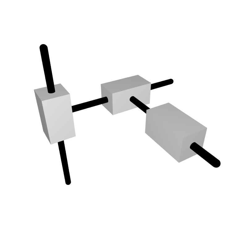
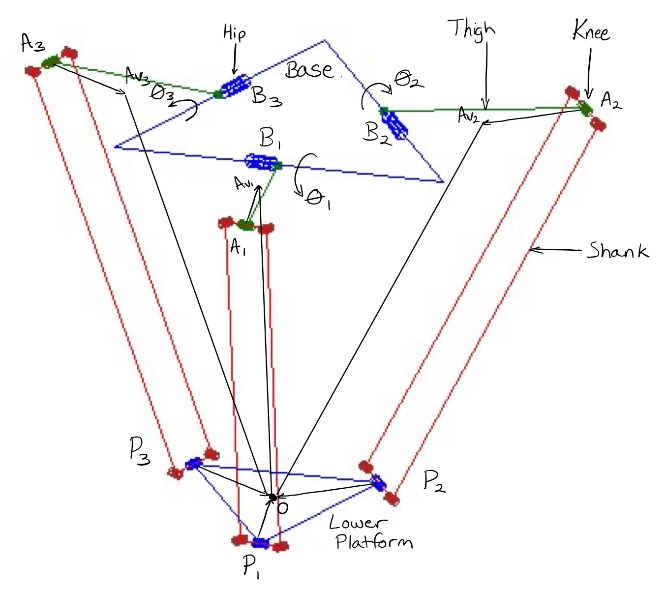
Kinematics for the Delta robot differ in calculation from those of other styles of robots. This applies to all parallel robots due to motion of each rotational joint being coupled to all other joints. The forward kinematics equations, which determine the position of the end-effector based on the joint variables, is described in this section. The angles of the revolute joints belongs to the set 𝚯 = [1 2 3]. The resulting position vector belongs to the set O = [x y z]. The calculation for forward kinematics of the Delta robot relies on the assumption that the base of the robot is always parallel to the lower platform (containing the end-effector) of the robot. First, we calculate vector corresponding to each of the “knee” locations on the Delta robot using the following equation:

where Ai describes the knee joint location for joint i, Bi is the distance from the center of the base to the servo motor for each hip joint i, and Li is the vector describing the position in space of the thigh of the delta robot. The parameter Li is dependent on the joint variable i, and is represented by the following three vectors:

Using these components, we can solve for the vectors A1 , A2 , and A3 , resulting in the following:

Finding the center point of the lower platform of the robot requires the definition of three spheres. The spheres will be defined as having their centerpoint at:

where Aiv is the centerpoint of the defined sphere, Ai is the vector describing the knee joint location for joint i, and Pi is the connection point between the shank and lower platform for each joint i. This equation gives us the center point of a sphere for each “limb” of the Delta robot, with a radius equal to the length of the shank. We can solve this equation and find the vectors A1v , A2v , and A3v :

The solution to the intersection point of the three defined spheres gives us the centerpoint of the lower platform, and subsequently the solution to the forward kinematics equations. This solution method yields two correct solutions for the intersection point of the three defined spheres, both of which can be applied depending on the configuration and geometric limitations of the Delta robot. Using these equations, a three-dimensional Cartesian coordinate can be assigned to the center point of the end-effector given the joint variables for each joint, or in practice, the angular position of the servo motor driving each limb of the Delta robot [10] [11].
6.2.2 Inverse Kinematics of the Delta Robot
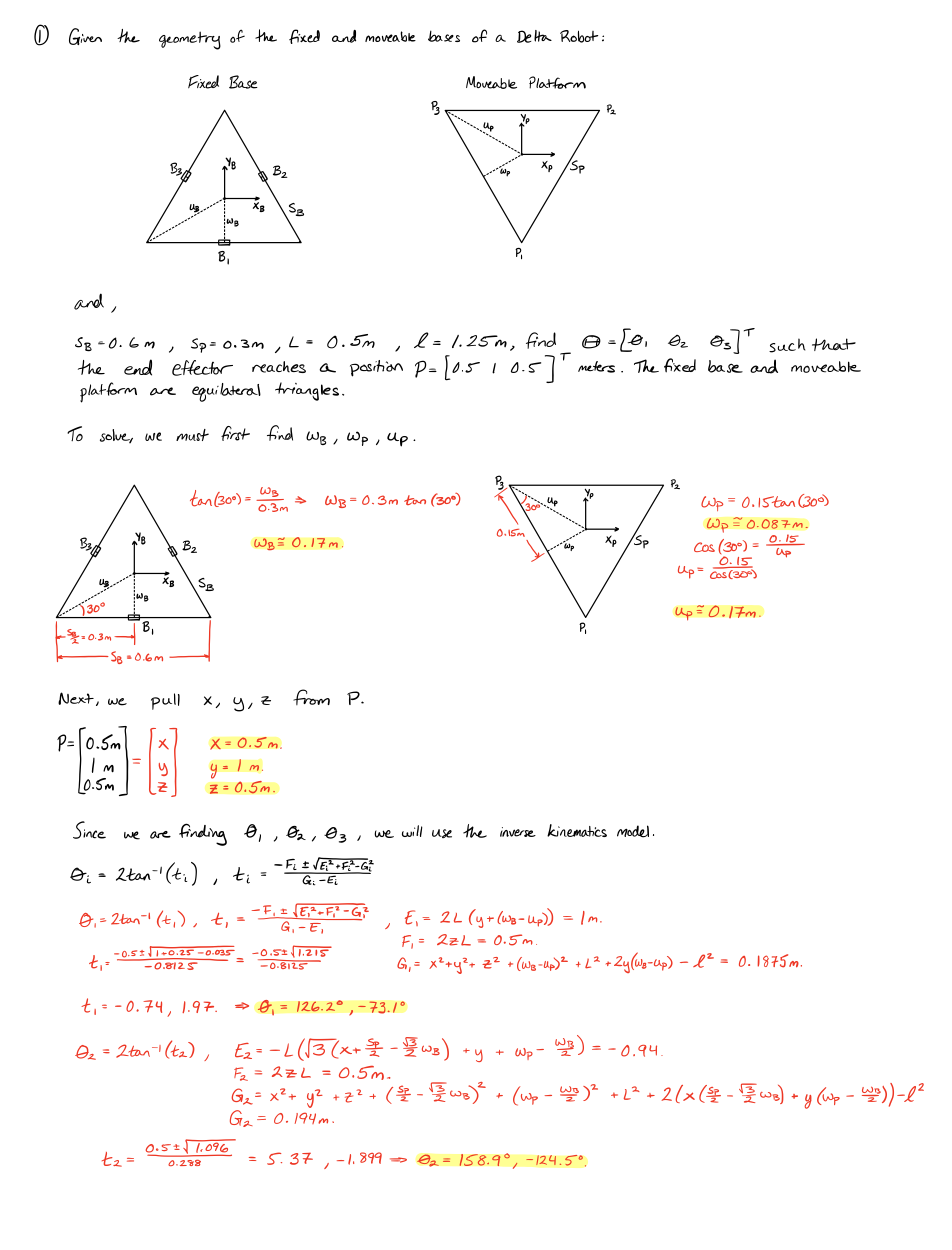
The inverse kinematics approach, where joint angles are calculated given the position of the end-effector, gives a more straightforward solution for position of the delta robot. This solution can be derived analytically using a set of three equations:

where,


and,

For each of these equations, we can solve for using the tangent half-angle substitution. In order to do this, we define:

From this, we can find:

Plugging these equations into our starting equations gives us:

6.2.3 Considerations for Motion Control
The Delta robot is driven by a controller that translates required motion behaviors to commands for the servo motors that introduce motion. These motion behaviors are typically determined by the customer (or end user), and the implementation of controllers to control the robot is done by an integrator (or other skilled controls technician). Due to the complexity of implementing specific motions, Controls Engineers will design programs to accommodate all motion cases that the robot will need to perform, and these motion cases will be selected by a Programmable Logic Controller (PLC) based on the criteria that are met. For example, if a peripheral vision system determines whether a part is moved to the right or left, these two movements will be programmed into the robot, and based on the output from the vision system, the PLC will select which movement is required. If a new movement, up in this case, is needed, a Controls Engineer (or skilled technician) will be required to program a new motion or set of motions for the robot. Though this is the case for most industrial robots, the structure of the Delta robot makes this endeavor much more involved.
When programming motion in a Delta robot, there are many considerations that need to be made. The first item that must be considered in motion control is the application of the robot. For pick-and-place applications, considerations for movement planning must first account for the beginning and end locations of the product to be transported and the path of motion required. Assembly applications must consider the path from the home position to the working position of the end-effector. Compound motion paths, though more difficult to program, are preferred when the task space is completely clear of obstruction, and a direct path from pick to place locations, or home to the working position, is permissible by constraints set by the customer. Paths of individual x, y, and z movements are simpler to program, but these paths take longer and require excess motion. These two items determine how quickly the robot can perform the task required, and are important considerations for motion planning. The integrator or programmer of the robot must also be mindful of the end-effector tooling, as tooling with air hoses requires that motion be conducted in a manner where forward motion is repeated in reverse to ensure that equipment does not become tangled or broken due to its fixed position on the end-effector in tandem with the motion of the end-effector.
6.3 Applications to Manufacturing
Decision criteria for which robot is best used in each manufacturing use case can typically conclude in multiple different robots for each application when these applications are relatively general. For example, picking and placing parts from a slow moving conveyor can be achieved by both SCARA and Delta robots, but the SCARA robot does not retain the expansion capacity of increased speed of the conveyor if this is deemed necessary in the future, a criterion achievable by the Delta robot in this situation. Specific applications best fit for the Delta robot are those that require high speed, accurate and precise movement, and do not require extensive movement in the XZ or YZ planes.

“TOSY Parallel Robot.JPG” by Humanrobo is licensed under CC BY-SA 3.0
6.3.1 End-effector Selection
The selection of end-effectors is critical to the overall function of a Delta robot for its selected application. Common end-effectors used with Delta robots are vacuum/pneumatic grippers, mechanical grippers, and other small tools. End-effectors are constrained by their maximum weight and size, as the delta robot requires a relatively low end-effector weight (<10kg).
Pneumatic grippers are commonly used for high-speed pick and place applications. Pneumatic grippers also prove useful when any product or packaging material around a product is flexible, as the pneumatic grippers typically include a rubber (or similar) suction cup that eases the mating of the grippers and products. This end-effector allows for slight error in end-effector placement while retaining the success of mating to the product being picked. This makes these end-effectors favorable in manufacturing environments in which runtime efficiency is critical.
Mechanical grippers are typically favorable in applications where complex mating surfaces exist, product weight is higher than the payload capacity of pneumatic grippers, or the product is prone to damage via vacuum. Though mechanical grippers are useful in these applications, they must be lightweight so as not to overload the Delta robot. Heavier mechanical grippers can be used, but this drastically reduces the maximum velocity the end-effector can reach. If the maximum velocity is decreased too much, another style of robots may be a better fit for the application instead of the Delta robot.
Precision tools for assembly are another category of end-effectors commonly used with Delta robots. These end-effectors include precision tools for mechanical assembly (precision screwdrivers, drills, fastening tools, etc.) as well as precision tools for assembly of electrical components (soldering equipment, placement of circuit components, circuit testing equipment, etc).
6.3.2 Peripheral Equipment
Delta robots are typically used in tandem with peripheral equipment to perform manufacturing tasks. Since one of the most common uses of Delta robots is material handling and pick-and-place applications, Delta robots are commonly used in conjunction with camera vision systems to identify the location and orientation of objects on stationary equipment or moving conveyors. These peripheral vision systems require integration with the robot to account for the data collected by the vision system, and incorporate this data into the motion control of the robot. Like vision systems, optical character recognition (OCR) and optical character verification (OCV) systems are commonly used with these types of robots to verify the presence of print such as expiration dates or batch codes on products while they are being processed by the Delta robot.
Conveyors are another common piece of peripheral equipment commonly used in conjunction with Delta robots. In manufacturing, Delta robot pick-and-place systems typically pick moving parts that are not arranged in any preset pattern to reduce the cost and necessity of upstream equipment to arrange or singulate products before traveling through the workspace of the robot. To achieve proper motion, the conveyor typically provides movement data of the conveyor to the robot for prediction of product speed if the product position is not taken at multiple sample points. These conveyor systems are extremely common in packaging applications, and are used in almost all applications in which products are not required to be under control of the machinery during the entire handling process.
6.4 Summary
The unique structure and highly adaptable use cases of the Delta robot lends itself to be a popular choice in many applications related to manufacturing. Their use of common controllers, motors, and peripheral equipment prepares them to be seamlessly integrated into complex systems purpose built for high speed manufacturing. Though control of these robots varies from that of a typical articulated or SCARA manufacturing robot, these manipulators can be applied to many use cases that require motion in the XY plane, but is constrained when movement in the XZ and YZ planes are required. The kinematics and programming of the Delta robot are complex in computation, but given these, the robot is simply implemented and dependent on few input parameters.
6.5 Practice Problems

References
[1] Gasparetto, A., and L. Scalera. “From the Unimate to the Delta Robot: The Early Decades of Industrial Robotics.” Explorations in the History and Heritage of Machines and Mechanisms, 2018, 284–95. https://doi.org/10.1007/978-3-030-03538-9_23.
[2] Collan, Mikael, and Karl-Erik Michelsen. “Robotics in Manufacturing – The Past and the Present.” Essay. In Technical, Economic and Societal Effects of Manufacturing 4.0: Automation, Adaption and Manufacturing in Finland and Beyond, 85–94. Cham, Switzerland: Palgrave Macmillan, 2020.
[3] Rey, L., and R. Clavel. “The Delta Parallel Robot.” Parallel Kinematic Machines, 1999, 401–17. https://doi.org/10.1007/978-1-4471-0885-6_29.
[4] Selitsky, Fridel. DeltaRamki. n.d. Wikimedia Commons. https://commons.wikimedia.org/wiki/File:DeltaRamki.gif.
[5] Smolenski, Nikola. Descartes Configuration. n.d. Wikimedia Commons. https://commons.wikimedia.org/wiki/File:Descartes_configuration.png.
[6] Smolenski, Nikola. SCARA Configuration. n.d. Wikimedia Commons. https://commons.wikimedia.org/w/index.php?curid=1624597.
[7] Auledas, Marc. Robot Delta FlexPicker D’ABB. n.d. Wikimedia Commons. https://commons.wikimedia.org/w/index.php?curid=107863685.
[8] Clavel, Reymond. Device for the movement and positioning of an element in space, issued December 11, 1990.
[9] Clavel, Reymond. “Conception D’un Robot parallèle Rapide à 4 degrés De Liberté.” Thesis, Verlag nicht ermittelbar, 1991.
[10] Williams II, Robert L. “The Delta Parallel Robot: Kinematics Solutions.” Ohio University Mechanical Engineering, October 2016.
[11] Zsombor-Murray, P.J. “Descriptive Geometric Kinematic Analysis of Clavel’s ‘Delta’ Robot.” McGill University. Accessed April 29, 2023. http://cim.mcgill.ca/~rmsl/cdenweb/cden_various_files/Delta-IK.pdf.
[12] TOSY Parallel Robot. n.d. Wikimedia Commons. https://commons.wikimedia.org/w/index.php?curid=18968956.
[13] Robotics Simulator: Simulation of the ABB IRB360 Robot in V-REP. YouTube. Coppelia Robotics, 2011. https://www.youtube.com/watch?v=kFrIsCp-OfQ.
Spong, Hutchinson, and Vidyasagar. Robot Modeling and Control. New York: John Wiley & sons, 2006.
